
Xn Handover Between Two OCUDU gNBs
Xn Handover Between Two OCUDU gNBs
This feature lives on the xnap_handover branch of OCUDU-RAN; the source document is docs/XN_HANDOVER.md. Related repositories: OCUDU-RAN (the RAN) and OCUDU-O1-Adaptor (the O1 adapter).
How It Works
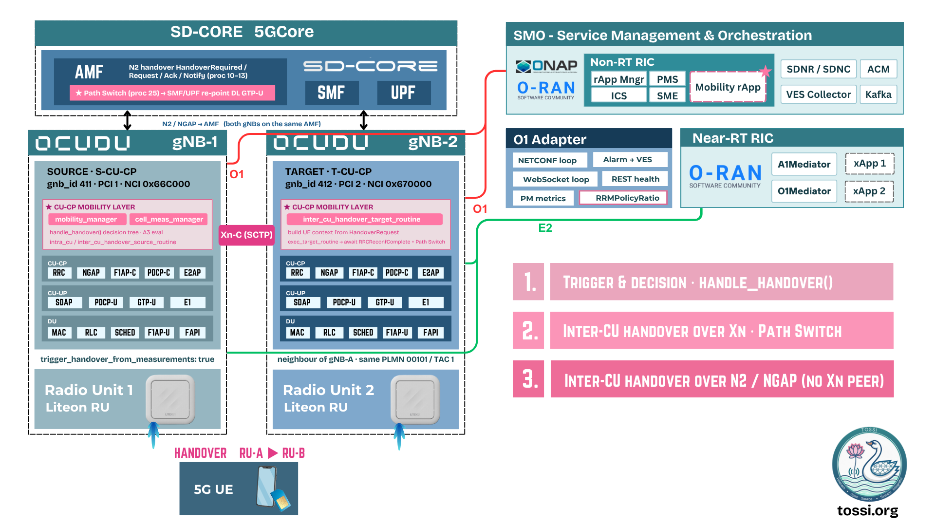
- Xn interface. Each gNB's CU-CP opens an SCTP Xn-C link to the peer (
cu_cp.xnap.gateways). On startup they exchange XnSetup and learn each other's gNB-ID and served cells. - Neighbour relations.
cu_cp.mobility.cellslists each gNB's own serving cell and the foreign (peer) cell. For the foreign cell,gnb_id_bit_lengthandnr_cell_idlet the CU-CP compute the peer's gNB-ID and route a handover to the correct Xn peer. - Decision and routing. When a handover is requested (manually, or from measurements), the mobility manager looks up the target cell's gNB-ID. If an Xn link to that gNB exists it runs an Xn handover; otherwise it falls back to an N2 (AMF-mediated) handover.
- Xn handover flow. The source sends HandoverRequest, the target admits and sets up F1/E1 bearers and returns HandoverRequestAcknowledge, the source sends the RRC reconfiguration (Handover Command) to the UE and transfers PDCP SN status over Xn, the target completes and issues an NGAP Path Switch to the AMF to repoint the downlink GTP-U path, and the source UE context is released over Xn.
- Measurements and KPIs. The UE's RRC MeasurementReports land in the CU-CP cell measurement manager, which can trigger A3 handovers and snapshots each UE's serving and neighbour RSRP/RSRQ/SINR (SSB and CSI-RS) into the CU-CP metrics as
cu-cp.meas_reports. That block streams out over the metrics WebSocket and is picked up by the O1 adapter.
Code entry points: lib/xnap/, lib/cu_cp/mobility_manager/, and lib/cu_cp/cell_meas_manager/.
Handover Message Sequence
The message exchange between the source gNB, target gNB, AMF, and UPF, in three phases.
Handover preparation
- UE to source gNB: Measurement Control and Reports.
- Source gNB: Handover Decision.
- Source gNB to target gNB: Handover Request.
- Target gNB: Admission Control.
- Target gNB to source gNB: Handover Request Acknowledge.
Handover execution
- Source gNB to UE: RAN handover initiation. The UE detaches from the old cell and synchronizes to the target cell.
- Source gNB to target gNB: Early Status Transfer, then SN Status Transfer. The target buffers user data from the source gNB.
- UE to target gNB: RAN handover completion, followed by Handover Success and SN Status Transfer back to the source.
Handover completion
- Target gNB to AMF: Path Switch Request.
- AMF to UPF: Path Switch in the UPF(s). The UPF sends an End Marker to the source gNB and user data to the target gNB.
- AMF to target gNB: Path Switch Request Acknowledge.
- Source gNB to target gNB: UE Context Release.
User data then continues via the target gNB.
Configuration
Two example configs (Liteon RU, TDD n78, 100 MHz) live in the configs/ directory:
| Config | gNB |
|---|---|
gnb_ru_liteon_tdd_n78_100mhz_xnap_gnb1.yml | gNB1: gnb_id 411, pci 1, cell 0x66C000 |
gnb_ru_liteon_tdd_n78_100mhz_xnap_gnb2.yml | gNB2: gnb_id 412, pci 2, cell 0x670000 |
Environment-specific values are placeholders you must fill in:
| Placeholder | Meaning |
|---|---|
x.x.x.x (amf) | AMF address and this gNB's N2 bind. Both gNBs point at the same core. |
x.x.x.x (xnap) | bind_addrs is this gNB's Xn IP; peer_addrs is the other gNB's Xn IP. |
x.x.x.x (cu_up.ngu) | This gNB's N3 IP. ext_addr is advertised to the UPF and must be reachable (used by Path Switch after handover). |
xx:xx:xx:xx:xx:xx | RU / DU MAC addresses (ru_ofh.cells). |
0000:51:xx.x | NIC PCIe addresses; must match the -a <pcie> entries in hal.eal_args. |
Key blocks (already wired up in both files):
cu_cp.xnap.gateways: the Xn-C SCTP link to the peer gNB.cu_cp.mobility.cells: own serving cell plus the foreign (peer) cell, withgnb_id_bit_length/pci/plmn/tac/ssb_arfcnso the CU-CP can resolve the peer gNB-ID.cu_cp.mobility.report_configs:report_cfg_id 1(periodical) andreport_cfg_id 2(A3 event-triggered).cell_cfg.ssb.offset_to_point_a+k_ssb+pdcch.common.coreset0_index: manual SSB placement, pinned to the same values on both gNBs so the two cells land at an identical SSB position (required for intra-frequency neighbour measurement).pcap.xnap_enable: true: captures Xn so you can verify handover signalling in Wireshark.
Notes:
- Manual SSB placement is all-or-nothing: set
offset_to_point_a+k_ssb+coreset0_indextogether, or none (to auto-derive). Both cells here pin the same trio. - Each
ru_ofh.cells[].network_interfacePCIe address must also appear inhal.eal_argsas a-a <pcie>entry.
How to Run
Build (on each server)
git clone https://github.com/TOSSI-Foundation/OCUDU-RAN
cd OCUDU-RAN
mkdir build && cd build
cmake -DENABLE_DPDK=ON ..        # DPDK is needed for the Liteon OFH (split 7.2) RU
make -j$(nproc)
Bring up the two gNBs
- Start your 5G core (AMF/UPF). Both gNBs register to the same AMF.
- gNB1 (server A):
sudo ./apps/gnb/gnb -c gnb_ru_liteon_tdd_n78_100mhz_xnap_gnb1.yml - gNB2 (server B):
sudo ./apps/gnb/gnb -c gnb_ru_liteon_tdd_n78_100mhz_xnap_gnb2.yml - Confirm the Xn (SCTP) link comes up and XnSetup succeeds between the two gNBs.
- Attach a UE to gNB1 (or gNB2). Note its C-RNTI (from the gNB console metrics or logs); you need it for a manual handover.
sudo is required for DPDK and real-time scheduling.
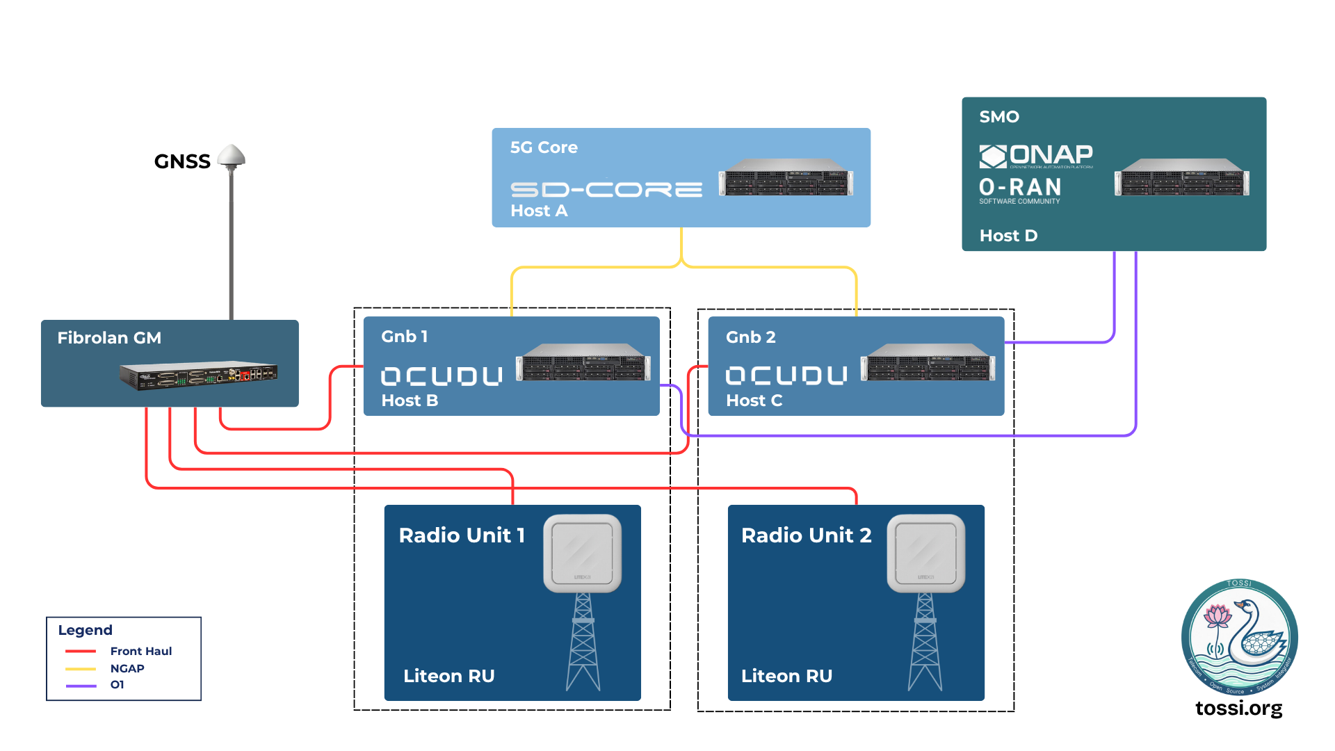
Testbed
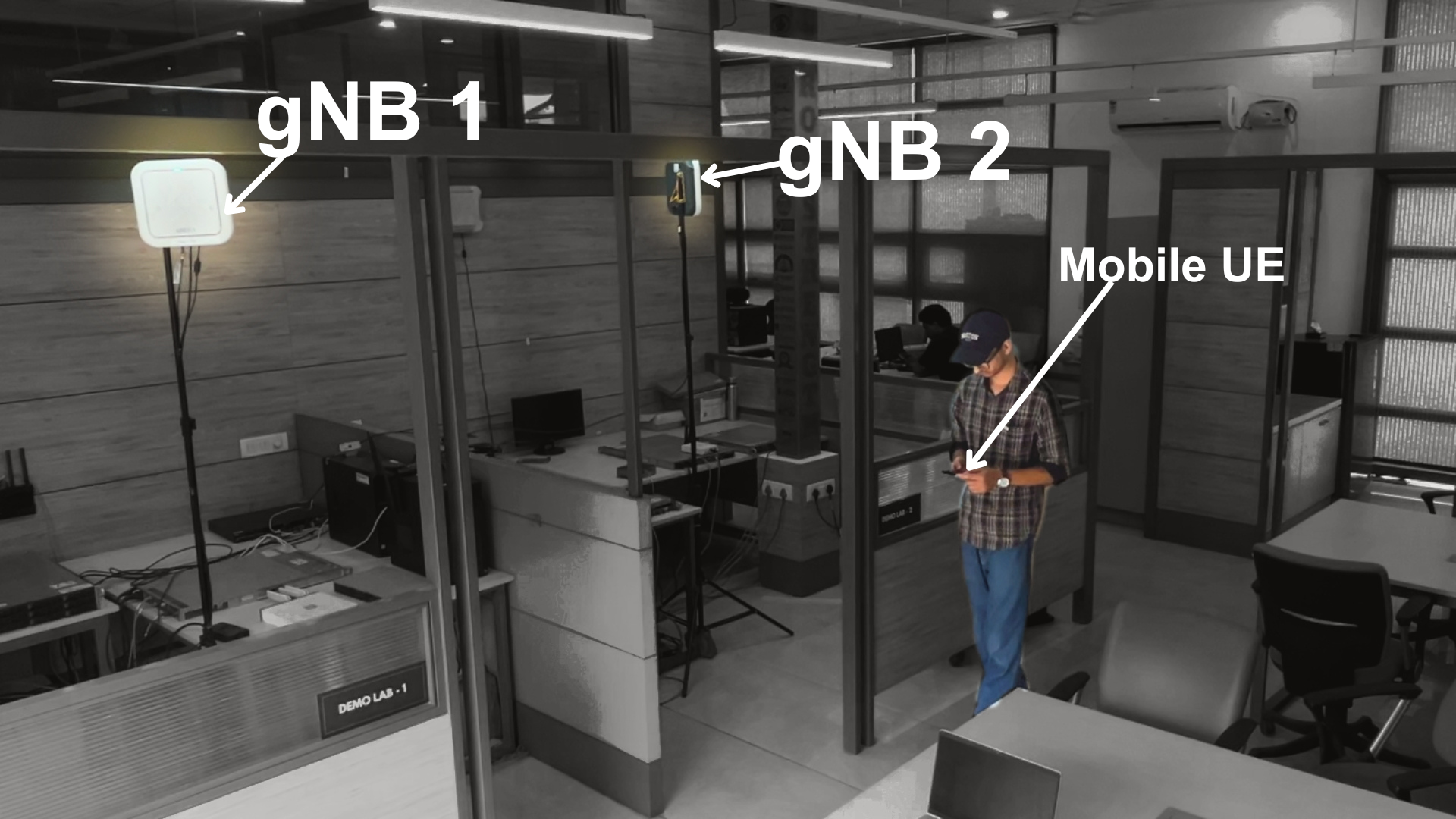
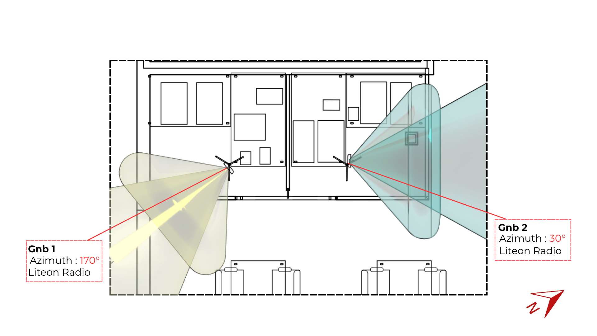
The two cells are deployed in an office lab as an intra-frequency pair so a mobile UE walking between them triggers a handover.
Triggering a Handover: Two Ways
Both paths drive the same Xn handover machinery; they differ only in what decides to hand over.
gNB-triggered (manual): the ho command
This is what the shipped configs are set for (cu_cp.mobility.trigger_handover_from_measurements: false). Type the command on the serving gNB's console (stdin):
ho <serving_pci> <rnti> <target_pci> <target_plmn> <target_tac>
serving_pci: PCI the UE is currently on (gNB1 =1, gNB2 =2).rnti: the UE's C-RNTI, in hex (e.g.4601).target_pci/target_plmn/target_tac: the destination cell (must be a configured Xn neighbour).
For example, to move a UE (rnti 0x4601) from gNB1 to gNB2, typed on gNB1's console:
ho 1 4601 2 00101 1
The manual ho works regardless of the trigger_handover_from_measurements flag. (Related console commands: cho ... for conditional handover with up to 8 candidates, release ... for RRC release / redirect.)
A3 event-triggered (measurement-based, automatic)
The network hands over on its own when the UE reports a neighbour is better than the serving cell (3GPP A3 event). To enable:
- Set
cu_cp.mobility.trigger_handover_from_measurements: true. - Keep the A3 report config (
report_cfg_id: 2,event_triggered_report_type: a3) and make sure each neighbour relation references it (report_configs: [2]); the shipped configs already do. - Tune the A3 thresholds (recommended, to avoid ping-pong):
meas_trigger_quantity_offset_db: how much better (dB) the neighbour must be (e.g.3).hysteresis_db: extra margin (e.g.0to2).time_to_trigger_ms: how long the condition must hold (e.g.100).
The shipped configs set these to
0(fire as soon as neighbour is greater than or equal to serving). Fine for a lab, too twitchy for real deployments.
Flow: the UE sends an RRC MeasurementReport when the A3 condition holds; the CU-CP cell measurement manager picks the strongest neighbour and, because trigger_handover_from_measurements is true, triggers the Xn handover to that neighbour's gNB automatically (no ho command needed).
Measurement-Report KPIs over O1
The same serving/neighbour measurements are exported as PM KPIs:
- RAN side. The CU-CP emits a
cu-cp.meas_reportsblock (per UE: serving / best-neighbour / neighbour cells, each with SSB and CSI-RS RSRP (dBm), RSRQ (dB), SINR (dB)) in its metrics JSON over the metrics WebSocket. Enable the WebSocket by turning onremote_controlin the gNB config (enabled: true,bind_addr,port). - O1 adapter side (OCUDU-O1-Adaptor): connects to that WebSocket and flattens the block into PM metrics named
cu-cp.meas.ue<ue>.<role>.pci<pci>.<quantity>(role =serving/best_neigh/neigh), pushing them to the SMO alongside the other PM KPIs.
Run the adapter (see the O1-Adaptor repo for full options):
python3 src/o1_adapter --profile gnb --netconf_host <host> --netconf_username <user> --netconf_password <pass>
References
- OCUDU-RAN
- OCUDU-RAN,
xnap_handoverbranch (this feature) - XN_HANDOVER.md (source document)
- OCUDU-O1-Adaptor